Plane Power 60 Amp Alternator Wiring Diagram
Wiring An Planepower 60a Altenator Vaf Forums

Dual Alternator Battery Isolator Wiring Diagram Car Alternator Alternator Repair

Wiring Diagram Toyota Alternator S Sense Wire Example Denso Alternator Denso Alternator Electrical Circuit Diagram

3 Wire Alternator Wiring Diagrams Google Search Alternator Car Alternator Toyota Corolla

27 Ford Alternator Wiring Diagram Internal Regulator Bookingritzcarlton Info Diagram Alternator Wire

Motor Wiring Denso 3 Wire Alternator Diagram Wirdig In Inside A Denso Alternator Alternator Car Alternator

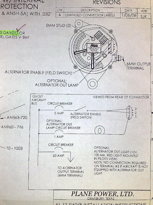
Plane power alternator wiring diagram interav alternator wiring diagram new hartzell alternator wiring diagram below is a picture a plane.
Plane power 60 amp alternator wiring diagram.

Voltage Regulator Alternator Wiring Diesel Forum Alternator Voltage Regulator Electrical Wiring Diagram

Headlight Relays And 3g Alternator The Swap 6 Ford Alternator Wiring Diagram Emprendedor Link Alternator Car Alternator Automotive Repair

Toyota Forklift Alternator Wiring Diagram Toyota Four Runner Hobby Electronics Electrical Safety Elec Alternator Denso Alternator Electrical Circuit Diagram
Ron Kilber S Logbook Aircraft Charging Systems

Alternator Wiring Problem Jeepforum Com Alternator Car Alternator Forklift
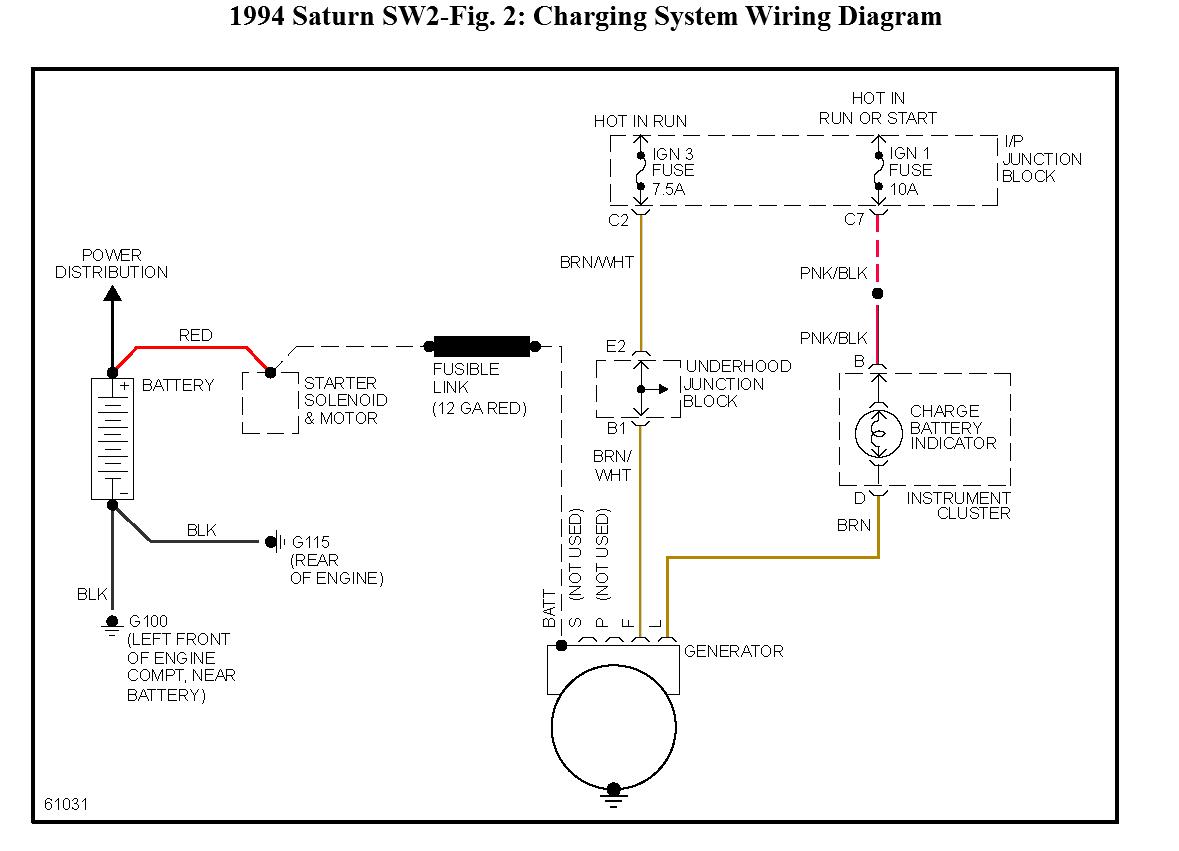
Diagram Aero Electric Alternator Diagram Full Version Hd Quality Alternator Diagram Modularorigamidiagrams Belleilmersion Fr
Https Planepower Aero Wp Content Uploads 2018 02 Stc Sa10921sc Afms 003 11 0000 Pp Pdf

Beautiful Sbc Alternator Wiring Diagram Diagrams Digramssample Diagramimages Wiringdiagramsample Electrical Circuit Diagram Alternator Electrical Diagram

Unique Vn Alternator Wiring Diagram Diagrams Digramssample Diagramimages Wiringdiagramsample Wiringdiagram Alternator Diagram Electrical Diagram

Bosch Internal Regulator Alternator Wiring Diagram Alternator Electric Motor Generator Alternator Working

How To Wire Ignition Switch For 3 Wire Alternator Google Search Chevy Diagram Wire

Ignition And Charging System Diagram Vw Engine Automotive Repair Auto Repair

Volvo Penta Fuel Pump Wiring Diagram Volvo Volvo Trucks Jeep Grand

Prestolite Alternator Wiring Diagram Marine In 2020 Alternator Car Alternator Electric Car Engine

How To Wire An Alternator Alternator Car Alternator Automotive Mechanic

Sbc Engine Test Stand Wiring Diagram Wiring Data Vw Engine Engine Stand Engineering

29 Ford Alternator Wiring Diagram Bookingritzcarlton Info Alternator Denso Alternator Wire
Alternator Warning Light Wiring Schematic And Wiring Diagram In 2020 Alternator Electrical Wiring Diagram Electrical Diagram
3
Source : pinterest.com
